

Price Sheet for China Hand-Made Spool Type Flanged Rubber Flexible Expansion Bellows
We’ve been committed to giving easy,time-saving and money-saving one-stop purchasing support of consumer for Price Sheet for China Hand-Made Spool Type Flanged Rubber Flexible Expansion Bellows, Your help is our everlasting electricity! Warmly welcome customers at your home and abroad to go to our enterprise.
We’ve been committed to giving easy,time-saving and money-saving one-stop purchasing support of consumer for China Expansion Bellows, Rubber Bellows, We now have the best solutions and skilled sales and technical team.With the development of our company, we are able to supply customers best products, good technical support, perfect after-sales service.
Details
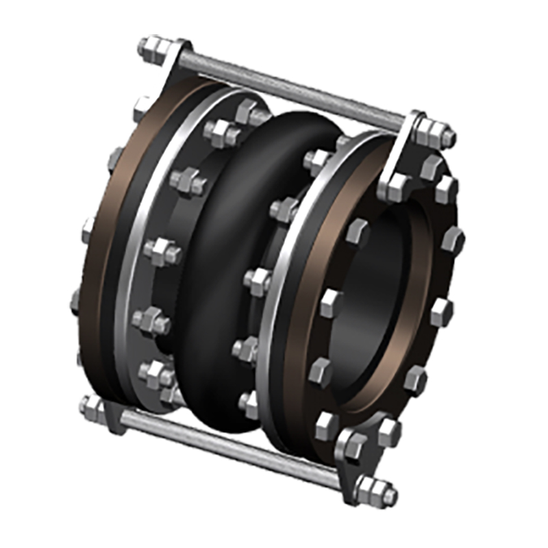
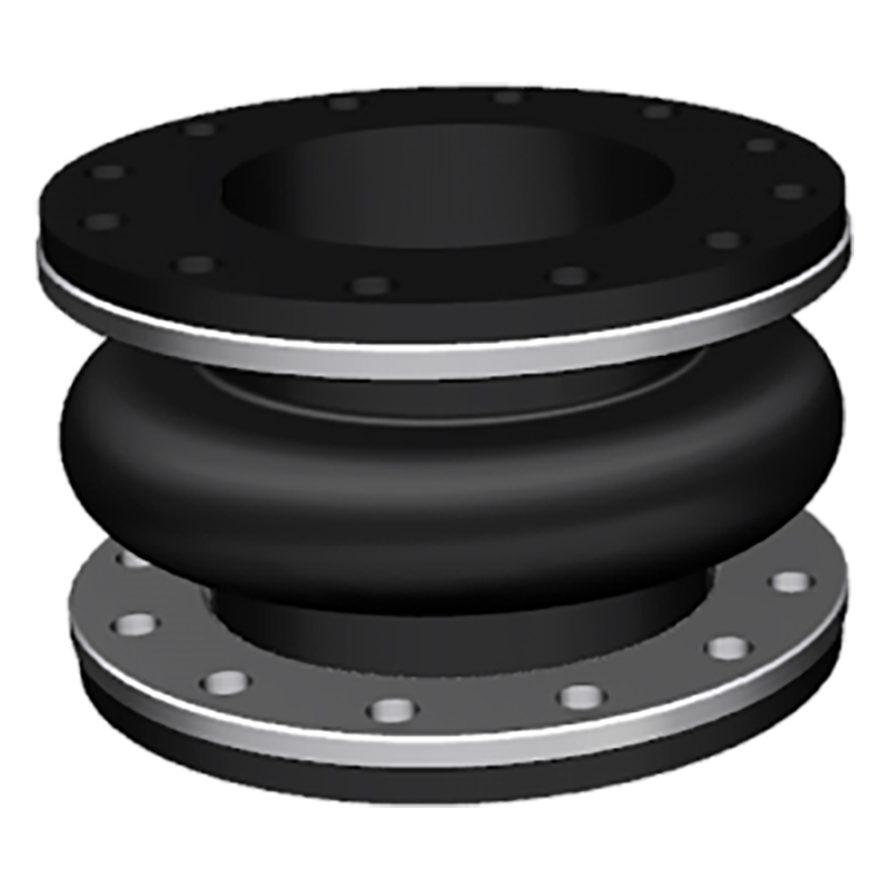
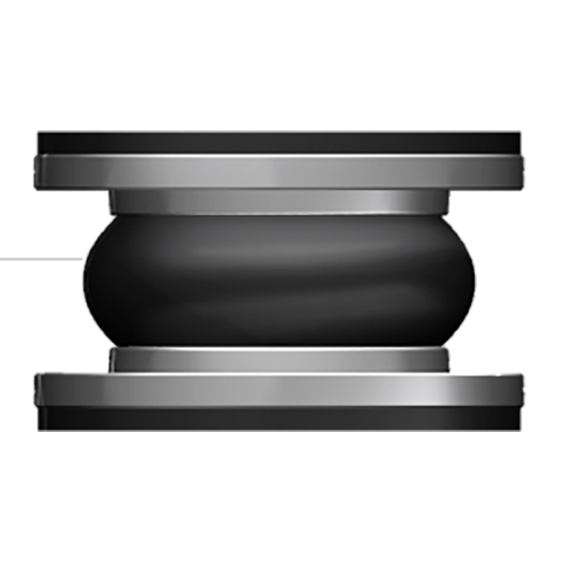
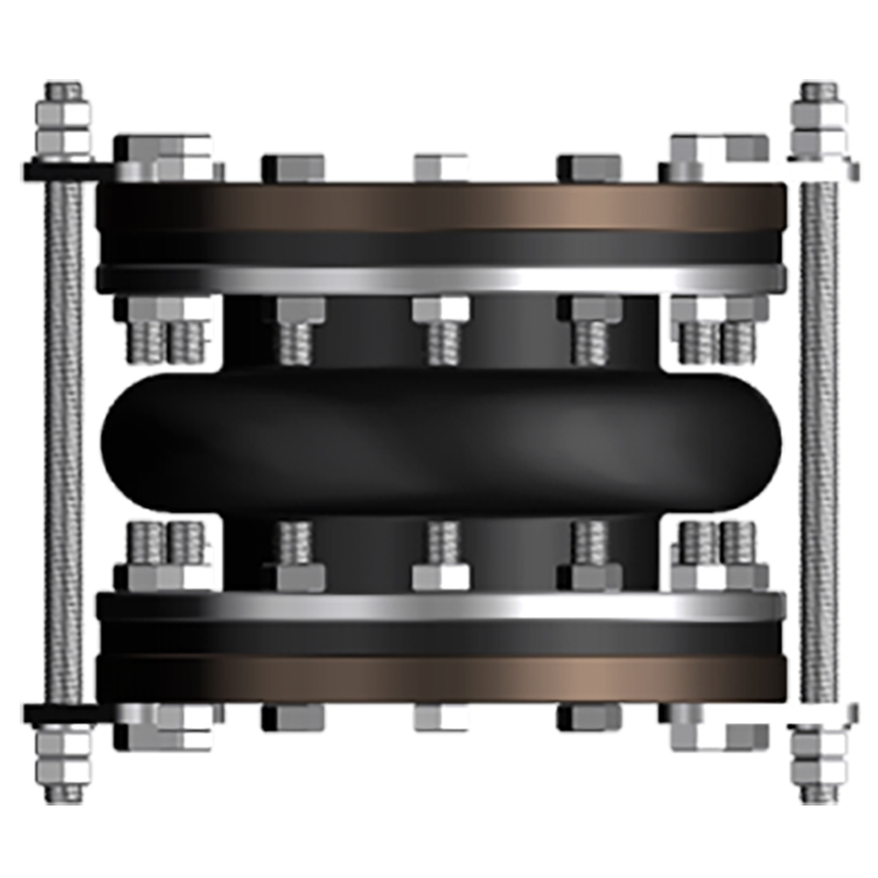
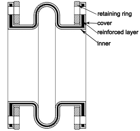
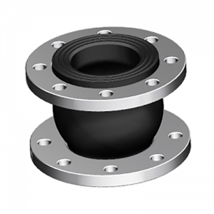
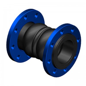
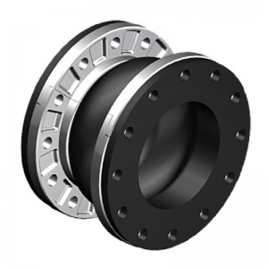
The spool type rubber joint is molded type, with a metal collar reinforced at the neck of the body. The ST stype uses a light reaining ring to support the integral flange. STF is filled arch, with 50% of the ST allowed movements, but it has 4 times spring rates than hollow arch.
| Specifications | I | II | III |
| Working Pressure Mpa (Kgf/Cm2) | 1Mpa (10) | 1.6 (16) | 2.5 (25) |
| Test Pressure | 1.5Mpa | 2.4Mpa | 3.75Mpa |
| Burst Pressure Mpa (Kgf/Cm2) | 3 (30) | 4.8 (48) | 5.5 (55) |
| Vacuum Kpa (Kgf/Cm2) | 53 (400) | 86(660) | 100 (750) |
| Materials | EPDM/NBR/SBR/NR | ||
| Diameter Range | DN15-DN600 (1/2″-24″) | ||
| Connection Method | FLANGETHREADCLAMP | ||
| Flanges Dimensions | DIN, EN,ANSI, BS, JIS and other standards | ||
| Applicable Medium | Air, compressed air, water, seawater, hot water, oil, acid, alkali etc. | ||
| Loading Port: | Qingdao, China | ||
| Shipment Terms: | FOB, CFR, CIF | ||
| Production Capacity: | 50000 set | ||
| Payment Terms: | L/C, T/T, D/P | ||
| Connection: | Flange, Thread | ||
| Flange Material: | Carbon Steel, Stainless Steel | ||
| Period of Delivery | about 21 working days | ||
|
SPOOL TYPE (ST) -American Standard ST |
||||||||||
|
Dimensions |
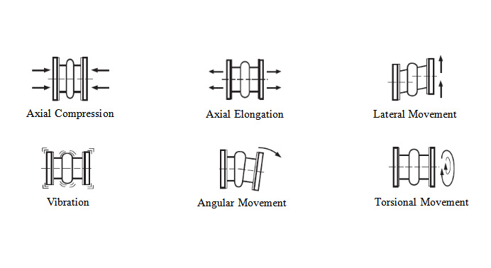
Movement Distance |
Operating Condition |
||||||||
|
Pipe Size |
O’all Length |
Flange OD |
Retaining Ring Thickness |
Axial Compression |
Axial Extension |
Lateral Deflection |
Angular Deflection |
Max w.p. (psi)-3,-4 |
Max Vacuum (in. of Hg)-5 |
|
|
Inch |
mm |
Inch |
Inch |
Inch |
Inch |
Inch |
Inch |
|||
|
2″ |
50 |
6″ |
6″ |
3/8″ |
7/16″ |
1/4″ |
±1/2″ |
19° |
150 |
26 |
|
2 1/2″ |
65 |
6″ |
7″ |
3/8″ |
7/16″ |
1/4″ |
±1/2″ |
15° |
150 |
26 |
|
3″ |
80 |
6″ |
7 1/2″ |
3/8″ |
7/16″ |
1/4″ |
±1/2″ |
13° |
150 |
26 |
|
4″ |
100 |
6″ |
9″ |
3/8″ |
7/16″ |
1/4″ |
±1/2″ |
10° |
150 |
26 |
|
5″ |
125 |
6″ |
10″ |
3/8″ |
7/16″ |
1/4″ |
±1/2″ |
8° |
150 |
26 |
|
6″ |
150 |
6″ |
11″ |
3/8″ |
7/16″ |
1/4″ |
±1/2″ |
6° |
150 |
26 |
|
8″ |
200 |
6″ |
13 1/2″ |
3/8″ |
11/16″ |
3/8″ |
±1/2″ |
6° |
150 |
26 |
|
10″ |
250 |
8″ |
16″ |
3/8″ |
11/16″ |
3/8″ |
±1/2″ |
5° |
150 |
26 |
|
12″ |
300 |
8″ |
19″ |
3/8″ |
11/16″ |
3/8″ |
±1/2″ |
5° |
150 |
26 |
|
14″ |
350 |
8″ |
21″ |
3/8″ |
11/16″ |
3/8″ |
±1/2″ |
4° |
150 |
15 |
|
16″ |
400 |
8″ |
23 1/2″ |
3/8″ |
11/16″ |
3/8″ |
±1/2″ |
4° |
150 |
15 |
|
18″ |
450 |
8″ |
25″ |
3/8″ |
11/16″ |
3/8″ |
±1/2″ |
3° |
150 |
15 |
|
20″ |
500 |
8″ |
27 1/2″ |
3/8″ |
13/16″ |
7/16″ |
±1/2″ |
3° |
150 |
15 |
|
24″ |
600 |
10″ |
32″ |
3/8″ |
13/16″ |
7/16″ |
±1/2″ |
3° |
150 |
15 |
|
SPOOL TYPE: FILLED ARCH (STF) -American Standard STF |
||||||||||
|
Dimensions |
Movement Distance |
Operating Condition |
||||||||
|
Pipe Size |
O’all Length |
Flange OD |
Retaining Ring Thickness |
Axial Compression |
Axial Extension |
Lateral Deflection |
Angular Deflection |
Max w.p. (psi)-3,-4 |
Max Vacuum (in. of Hg)-5 |
|
|
Inch |
mm |
Inch |
Inch |
Inch |
Inch |
Inch |
Inch |
|||
|
2″ |
50 |
6″ |
6″ |
3/8″ |
7/32″ |
1/8″ |
±1/4″ |
9.5° |
150 |
26 |
|
2 1/2″ |
65 |
6″ |
7″ |
3/8″ |
7/32″ |
1/8″ |
±1/4″ |
7.5° |
150 |
26 |
|
3″ |
80 |
6″ |
7 1/2″ |
3/8″ |
7/32″ |
1/8″ |
±1/4″ |
6.5° |
150 |
26 |
|
4″ |
100 |
6″ |
9″ |
3/8″ |
7/32″ |
1/8″ |
±1/4″ |
5° |
150 |
26 |
|
5″ |
125 |
6″ |
10″ |
3/8″ |
7/32″ |
1/8″ |
±1/4″ |
4° |
150 |
26 |
|
6″ |
150 |
6″ |
11″ |
3/8″ |
7/32″ |
1/8″ |
±1/4″ |
3° |
150 |
26 |
|
8″ |
200 |
6″ |
13 1/2″ |
3/8″ |
11/32″ |
3/16″ |
±1/4″ |
3° |
150 |
26 |
|
10″ |
250 |
8″ |
16″ |
3/8″ |
11/32″ |
3/16″ |
±1/4″ |
2.5° |
150 |
26 |
|
12″ |
300 |
8″ |
19″ |
3/8″ |
11/32″ |
3/16″ |
±1/4″ |
2.5° |
150 |
26 |
|
14″ |
350 |
8″ |
21″ |
3/8″ |
11/32″ |
3/16″ |
±1/4″ |
2° |
150 |
15 |
|
16″ |
400 |
8″ |
23 1/2″ |
3/8″ |
11/32″ |
3/16″ |
±1/4″ |
2° |
150 |
15 |
|
18″ |
450 |
8″ |
25″ |
3/8″ |
11/32″ |
3/16″ |
±1/4″ |
1.5° |
150 |
15 |
|
20″ |
500 |
8″ |
27 1/2″ |
3/8″ |
13/32″ |
7/32″ |
±1/4″ |
1.5° |
150 |
15 |
|
24″ |
600 |
10″ |
32″ |
3/8″ |
13/32″ |
7/32″ |
±1/4″ |
1.5° |
150 |
15 |
Products categories
-
Europe style for China Single Sphere/Arch Rubbe...
-
One of Hottest for China EPDM Single Arch Rubbe...
-
Europe style for China Supplier Double Ball Twi...
-
IOS Certificate China Heavy Duty Rubber Expansi...
-
Factory wholesale China Single Sphere Molded Ru...
-
Hot New Products China Double Arch Bellows Expa...


